Noise & Signal Considerations

To ensure clarity of signal from your encoder, and avoid excessive electrical noise, there are several options and installation considerations to take into account. Electrical noise must be mitigated, and there are several strategies to do that. The encoders’ cables are another important consideration, with cable length, termination, and connections all playing a part in keeping a signal “clean.” There are also additional methods to reduce noise. This white paper will focus on strategies and ways to reduce noise and signal distortions to ensure the signal from your encoder remains clean and uncorrupted.

Electrical Noise
Encoder – A Definition:
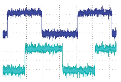
An encoder is an electro-mechanical transducer that converts mechanical rotary motion into digital signals for the control of machinery. The encoder produces a square wave signal as the shaft rotates. Speed, position, servo feedback, etc., can be determined through proper processing of this signal. As the electrical signal leaves the encoder, it is “clean” of electrical noise. However, by the time the signal reaches its intended counter, PLC, etc., it may be degraded and may not be “clean” enough for the system to work properly.
Electrical Noise:
A common cause of signal degradation is electrical noise. The longer the cable run, the more electrically induced noise the cable picks up. If this noise becomes excessive, miscounts will occur. Electrical noise causes miscounting because the receiving device cannot tell if an input signal is a valid encoder signal or a noise pulse. Normally there is sufficient input signal conditioning, or filtering, to take care of this problem.
However, filtering at the input of the receiving device will reduce the speed at which the system can operate. Years ago, most counters had high frequency limitations of between 5 and 20 kHz. Speed is now the name of the game, and these frequency limitations are simply not acceptable in today’s production environments. Electrical noise generated by AC power, electric motors, fluorescent lighting, relays, and many other sources can cause a plethora of problems in electrical systems. For the encoder in your system these problems can range from simple miscounting to a complete servo system lockup.
Electrical noise typically enters a system as one of two types: radiated and conducted. Radiated noise propagates through the air, while conducted noise finds an electrical path onto the encoder cables from ground loops, power supplies, or other equipment connected to the system.

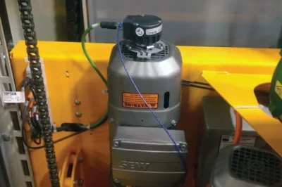
Model 25H Encoder mounted on a motor
1. Differential Signals
One method to alleviate the problem of electrical noise is using what is called differential signals. With differential signals, the output from the encoder is “split” into two signals that are exactly 180 degrees out of phase with each other. This is also called complementary signals, because one signal is the complement, or mirror image, of the other. As long as the two signal conductors are next to each other, any noise picked up by the cable will have equal and in-phase components on each conductor in the cable. Using differential input circuitry, the input will recognize only the DIFFERENCE between the signals. As one signal line is in a high, or logic 1 state, the complement is at a low, or logic 0 state. The differential input circuitry will accept this as a legitimate signal, and the in-phase noise products are simply ignored.
To use this type of noise immunity, the encoder must have what we refer to as a line driver output circuit. However, having the line driver output circuit is only half of the equation. Transmitting the signal in differential form is not enough; it must also be received in differential form. To accomplish this, the receiving device must also have a differential input circuit, or what is commonly called a “line receiver” input.
Many people believe that by specifying the differential output on the encoder, their noise problems will simply go away. However, without the proper line receiver input circuitry, it is a waste of money, and may even be worse from a noise standpoint. If the differential output of the encoder is not properly terminated, ringing and other spurious oscillations will appear on the signal lines.
Encoder Products offers differential output circuitry on most models. It operates over the voltage range of 5 to 28 volts DC supply voltage. The older standard for differential signals (also known as RS-422) called for 5-volt operation. By raising the voltage in the system, a much better signal to noise ratio results. In a 5-volt system with 3-volt spikes, the spikes are nearly as great as the desired signal amplitude. In the same setup with the voltage increased to 24-volts, for example, it is easy to see that the same 3-volt spikes can be easily ignored. However, it is important to remember the input circuitry must also be able to handle this higher voltage.

Cable Termination
2. Cable Considerations:
Cable Lengths
All cables have small amounts of capacitance between adjacent conductors. This capacitance is a direct function of the cable’s length, and tends to round off the leading edge of the square wave signal, increasing rise times. It can also distort the signal to the extent of causing errors in the system.
Signal distortion is not usually significant for lengths less than 30 feet (or 1000 picofarads). To minimize the distortion, use low capacitance cable (less than 30 picofarads per foot), in the shortest length possible for the application. To minimize distortion for cable lengths in excess of 30 feet, use differential line driver outputs, along with differential type receiver circuitry.
Also, a low capacitance twisted-shielded pair cable should be used whenever using differential signals. For high frequency applications (> 200kHz), this type of cable may be needed for all lengths.
Cable Termination
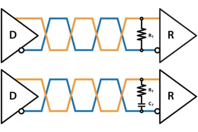
Proper cable termination is vital with differential signals. With an un-terminated configuration, signal reflections can occur, resulting in severely distorted waveforms. If signal distortion occurs, try parallel termination, which involves placing a resistor across the differential lines at the far (receiver) end of the line. The parallel termination resistor value (RT) should match the characteristic impedance (ZO) of the cable, typically 70-150 Ω. This permits higher frequencies to be transmitted without significant distortion.
It is usually better to select a value for RT that is slightly larger (up to 10% larger) than ZO, as over-termination tends to improve signal quality better than under-termination.
Unfortunately, low valued resistors can increase the power dissipated by the line driver, and reduce output signal swing. In this case, a capacitor should be placed in series with the resistor. The capacitor value should be equal to the round trip delay of the cable divided by the cables cable’s ZO. Round trip delay is equal to two times the cable length multiplied by 1.7ns/ft.
CT ≤ Round Trip Delay / ZO
Example:
Cable Length = 100 ft
Signal Velocity = 1.7 ns/ft
ZO = 120 Ω
CT ≤ (100ft x 2 x 1.7ns/ft) / 120 Ω
CT ≤ 3,000 pF
Note that the RC time constant of this type of termination can reduce the system frequency response.
A parallel termination resistor value larger than listed above can often provide adequate reduction of signal reflections, and still maintain adequate frequency response, and low power dissipation. Experimentation is often required for each application consisting of long cable runs and high frequencies.
Cable Connection
It is important to connect cable shields to ground on the instrument end (counter, PLC, etc.). Always properly ground the motor/machine for which the encoder is mounted. Also, ground the encoder case under the following conditions:
(1) DO NOT ground the encoder case through both the motor/machine and the cable wiring, and
(2) DO NOT allow the encoder cable wiring to ground the motor/machine exclusively. High motor/machine ground currents could flow through encoder wiring, potentially damaging the encoder and associated equipment.
Additional Methods to Reduce Noise:
There are several additional methods that can reduce noise in an encoder’s electrical signal:
- Route power and signal lines separately.
- Twist and shield signal lines, and place signal lines at least 12 inches from other signal lines and from power leads.
- Maintain signal wire continuity from the encoder to the controller/counter (i.e., avoid junctions or splices).
- Provide clean regulated power to encoder and associated equipment (± 2%).
- Ensure equipment (motors, drives, shafts, etc.) is properly grounded.
- Connect encoder cable shield to ground at controller/counter end, leaving the end near the encoder disconnected.
- If possible, use differential line driver signal outputs with high-quality twisted, shielded pair cable. The complimentary signals greatly reduce common mode noise levels, as well as signal distortion resulting from long cable lengths.
![]() Noise and Signal Distortion Considerations
Noise and Signal Distortion Considerations
