Tempco Duct Heaters: Standard & Finned Tubular

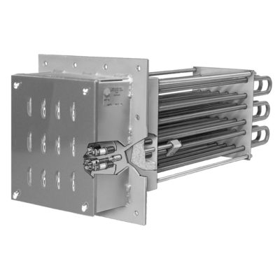
Heavy wall Incoloy® tubular heating elements (field replaceable) provide protection against corrosive air environments and resistance to vibration when compared to open coil elements. Air duct heaters can be designed specifically for high pressure and/or hazardous locations. Turnkey systems including the duct heater, power and temperature control panel, and the temperature and over-temperature sensors can also be provided.
Design Features: Standard Tubular Duct Heaters
- NEMA 1 General Purpose Ventilated Enclosure
- Painted Steel Mounting Flange
- Single- and Three-Phase Wiring
- 3-1/2″ (89 mm) Insulation
- Field Replaceable Incoloy® 840 Elements
- Element Bends Re-pressed
- 1/4″ (6 mm) Inside Diameter Thermowell
- Stainless Steel Support Plate and Corner Posts
Design Features: Finned Tubular Duct Heaters
- NEMA 1 General Purpose Ventilated Enclosure
- Stainless Steel Mounting Flange and Terminal Box
- Single- and Three-Phase Wiring
- 1″ (25 mm) Insulation
- Field Replaceable .430 Diameter Stainless Steel Elements
- 9/32″ (7 mm) ID Sensor Thermowell
- Stainless Steel Support Plate and Corner Posts
- Stainless Steel Insulation Housing
Eagle Sensors & Controls, Division of Excel Automation LLC, is an authorized Tempco distributor. Contact us for sales & technical support for Tempco heaters, Tempco sensors, Tempco temperature controllers, Tempco process heating systems & all other Tempco products.
Sizing a Duct Heater
To properly match a duct heater to an application, the wattage, air velocity and element watt density must be determined.
Formulas and graphs that will aid in your design include:
- Wattage calculation formulas and table
- Element Watt Density vs. Sheath Temperature and Air Velocity Graph
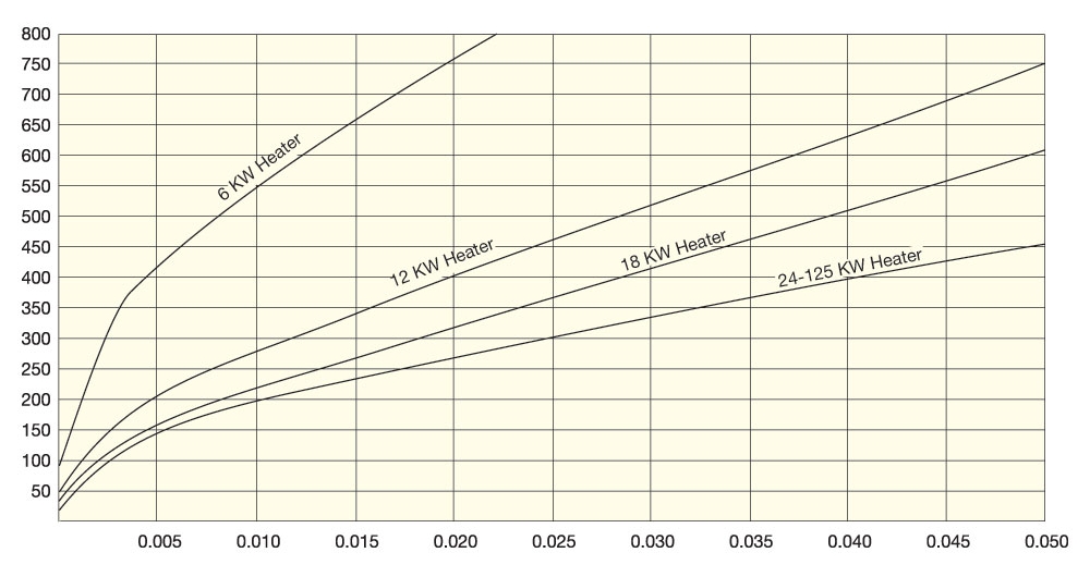
- Pressure Drop vs. Air Velocity Graph
In most applications the following design limitations should be adhered to:
- Maximum watt density of 40 watts/in2 (6.2 watts/cm2 )
- Maximum element sheath temperature of 1400°F (760°C)
- Minimum air velocity of 200 feet per minute (61 meters per minute)
- Maximum voltage for UL certified heaters is 480V.
- Maximum voltage for CSA certified heaters is 600V.
Calculating Minimum Wattage Requirement
This table is for quick-estimation purposes and is based on air under standard conditions (70°F inlet air temperature at 14.7 PSIA).
If flow is given in CFM at operating temperature and pressure it can be converted to SCFM (Standard Cubic Feet per Minute) with the following formula (use the equations to the right for compressed air):

P = operating pressure (gauge pressure + 14.7)
T = operating temperature
Note: Remember when calculating wattage to use the maximum anticipated air flow and to compensate for any heat losses.
For free air use equations:


For compressed air use equations:


KWH to Heat Air at Selected Flow Rates
| Amt. of Air CFM |
Temperature Rise (°F) | ||||||||||
|---|---|---|---|---|---|---|---|---|---|---|---|
| 50 | 100 | 150 | 200 | 250 | 300 | 350 | 400 | 450 | 500 | 600 | |
| Kilowatt Hours to Heat Air | |||||||||||
| 100 | 1.7 | 3.3 | 5 | 6.7 | 8.3 | 10 | 11.7 | 13.3 | 15 | 16.7 | 20 |
| 200 | 3.3 | 6.7 | 10 | 13.3 | 16.7 | 20 | 23.3 | 26.7 | 30 | 33.3 | 40 |
| 300 | 5.0 | 10 | 15 | 20 | 25.0 | 30 | 35.0 | 40.0 | 45 | 50.0 | 60 |
| 400 | 6.7 | 13.3 | 20 | 26.7 | 33.3 | 40 | 46.7 | 53.3 | 60 | 66.7 | 80 |
| 500 | 8.3 | 16.7 | 25 | 33.3 | 41.7 | 50 | 58.3 | 66.7 | 75 | 83.3 | 100 |
| 600 | 10 | 20 | 30 | 40 | 50.0 | 60 | 70.0 | 80.0 | 90 | 100 | 120 |
| 700 | 11.7 | 23.3 | 35 | 46.7 | 58.3 | 70 | 81.7 | 93.3 | 105 | 116.7 | 140 |
| 800 | 13.3 | 26.7 | 40 | 53.3 | 66.7 | 80 | 93.3 | 106.7 | 120 | 133.3 | 160 |
| 900 | 15 | 30 | 45 | 60 | 75.0 | 90 | 105 | 120 | 135 | 150 | 180 |
| 1000 | 16.7 | 33.3 | 50 | 66.7 | 83.3 | 100 | 116.7 | 133.3 | 150 | 166.7 | 200 |
| 1100 | 18.3 | 36.7 | 55 | 73.3 | 91.7 | 110 | 128.3 | 146.7 | 165 | 183.3 | 220 |
| 1200 | 20 | 40 | 60 | 80 | 100 | 120 | 140 | 160 | 180 | 200 | 240 |
Note: For additional information or help with your application please contact TEMPCO.
Element Watt Density vs. Air Temperature and Air Velocity
Use graph (English or Metric) to plot Outlet Air Temperature vs. Outlet Air Velocity to determine Element Watt Density.
The recommended watt density is based on a maximum element sheath temperature of 1400°F (760°C). Air and other gases that are poor conductors of heat require watt densities matched to the velocity of the gas flow to prevent element overheating. Selecting a lower watt density for the heating elements will extend heater life expectancy.
Element Watt Density is the wattage dissipated per square inch of the element sheath surface and is calculated with the following formula.

Air Velocity (feet per minute)
English
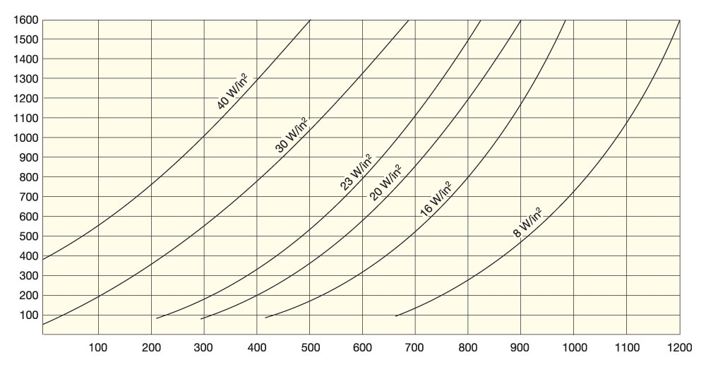
Process Temperature °F – Approximate Sheath Temperature 1400°F
Air Velocity (meters per minute)
Metric
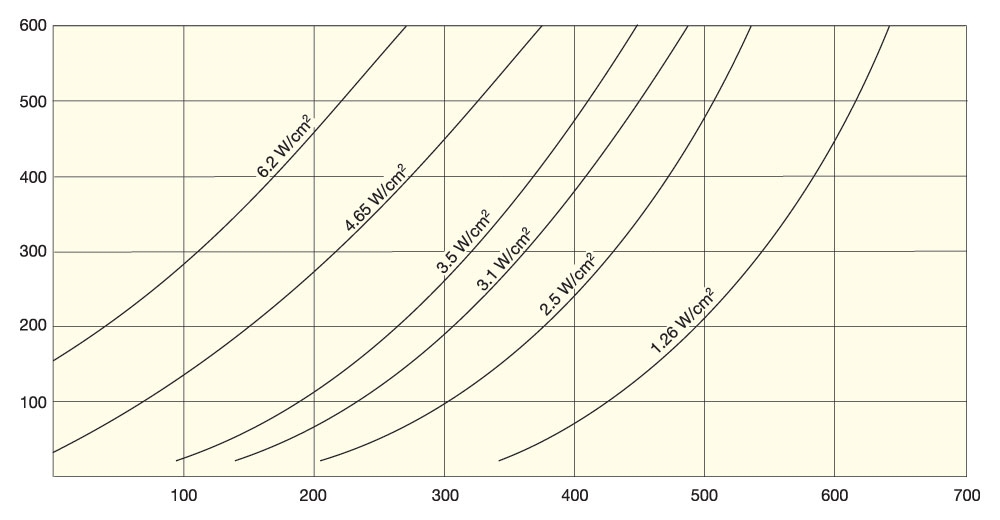
Process Temperature °C – Approximate Sheath Temperature 760°C
Element Watt Density vs. Sheath Temperature and Air Velocity
Use graph (English or Metric) to plot Watt Density vs. Air Velocity to determine Sheath Temperature.
Use graph (English or Metric) to plot Watt Density vs. Sheath Temperature to determine the required Air Velocity.
Watt Density (W/in2)
English
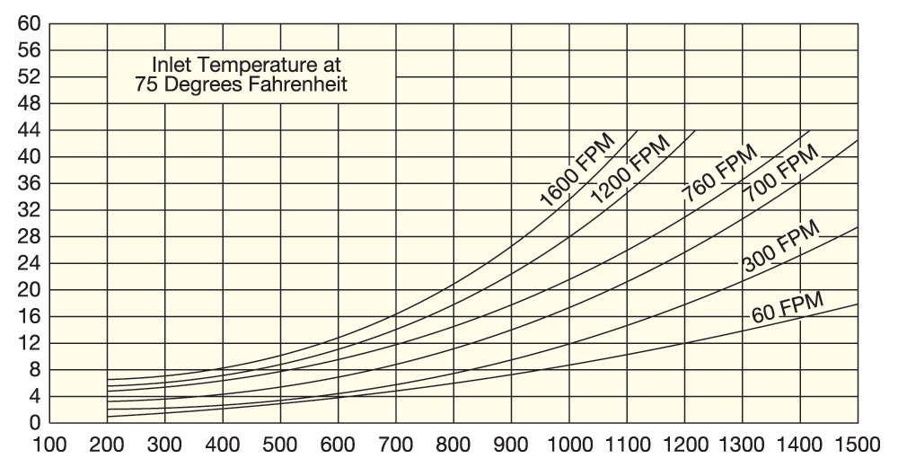
Sheath Temperature (°F)
Watt Density (W/cm2)
Metric
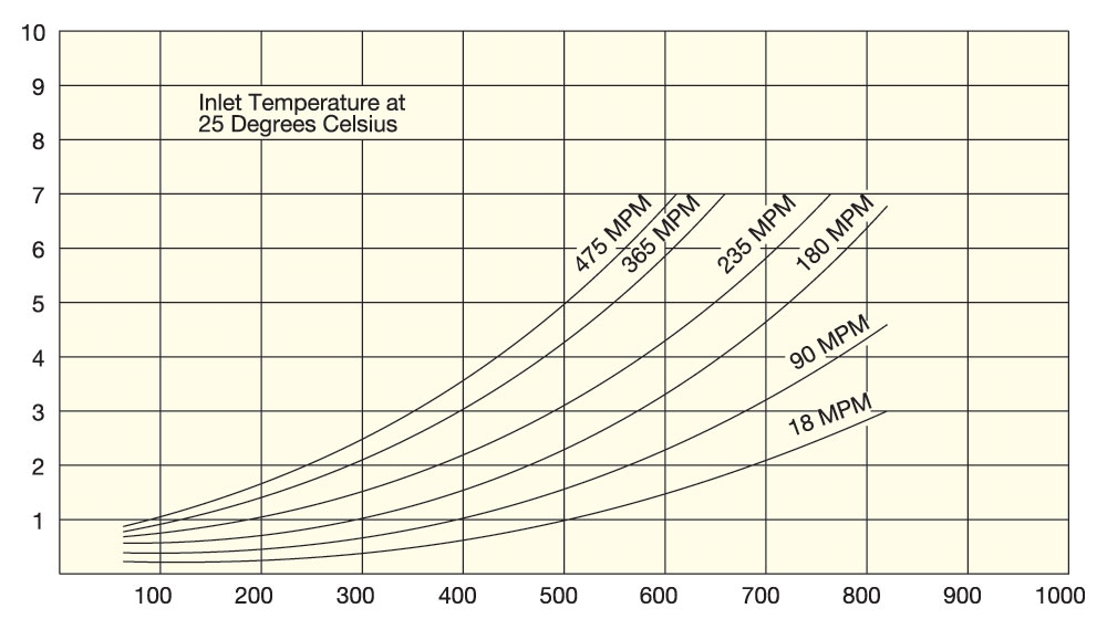
Sheath Temperature (°C)
Pressure Drop vs. Air Velocity
Use graph (English or Metric) to plot Pressure Drop vs. Air Velocity for standard duct heater sizes used to properly Size Blowers.

Air Velocity (feet per minute)
English
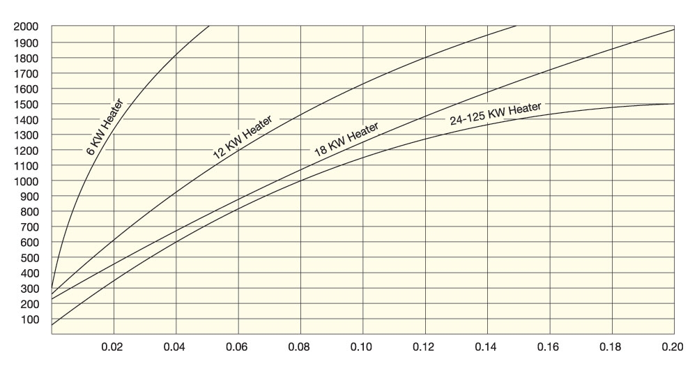
Approximate Pressure Drop (inches of water)
Air Velocity (meters per minute)
Metric
