Tempco Clamping Options

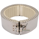
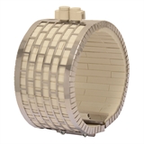
Type B – Built-In Bracket (Standard), Two-Piece Band
The Built-In Bracket is the basic design most often specified by OEMs and processors. The standard screw used is 1/4-20. It is available with all types of insulation, construction styles, and termination variations.
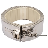
Type S – Built-In Bracket with Spring-Loaded Screw, One-Piece Band
The Built-In Bracket can also be supplied with a spring-loaded screw. The spring-loaded clamp aids in absorbing thermal expansion.
Type S – Built-In Bracket with Spring-Loaded Screw, Two-Piece Band
The Built-In Bracket can also be supplied with a spring-loaded screw. The spring-loaded clamp aids in absorbing thermal expansion.
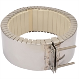
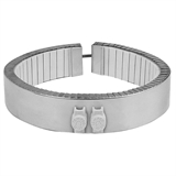
Type L – Latch and Trunnion, One-Piece Band
The spring-loaded latch and Trunnion clamping system is ideal for bands over 12″ in diameter to absorb thermal expansion and facilitate installation on large bands.
The Latch and Trunnion clamping system is available with all types of insulation, construction styles, and termination variations.
Type L – Latch and Trunnion, Two-Piece Band
The spring-loaded latch and Trunnion clamping system is ideal for bands over 12″ in diameter to absorb thermal expansion and facilitate installation on large bands.
The Latch and Trunnion clamping system is available with all types of insulation, construction styles, and termination variations.
Type F – Bent-Up Flange (Ears), Two-Piece Band
The Bent-Up Flange (Ears) design is available with all types of insulation, construction styles, and termination variations.
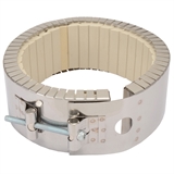
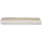
Shell Overlap, Two-Piece Band
The Shell Overlap design is the preferred method of providing a thermocouple mounting hole in a ceramic band heater. It is available with all types of insulation, construction styles, clamping and termination variations.
Additional Options
Optional Double Insulation (D): 1/2
Standard built-In ceramic fiber insulation 1/4″ thick on all Ceramic Bands; will reduce power consumption by 25 to 30 percent and lower external temperatures (when compared to uninsulated band heaters).
Optional built-in ceramic fiber insulation 1/2″ thick is available; for situations requiring additional insulation for lower external temperatures and increased electrical energy savings. This will decrease power consumption by 35 to 37 percent (when compared to uninsulated band heaters).
Type R: Uninsulated Ceramic Band Heaters
This system was developed to provide another means of heating and cooling high-temperature extrusion processes. To reduce the cost and weight of typical shroud systems, Tempco developed a low mass, non-thermally insulated ceramic band heater to work in tandem with a highly efficient stainless steel sheet metal shroud for high-temperature heating and cooling extrusion processes. Forced air blowers are used for cooling. The ambient airflow enters the shroud, circulates around the ceramic heater and barrel, removes the heat from the heater and the process, and exits the shroud opposite the entrance port.
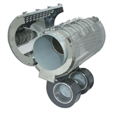
Type RCC: (Ribcage) Heating Mounting Configuration
Type RCC (Rib Cage) Air-Cooled System uses multiple Type R Ceramic Band Heaters under one air-cooled shroud. Type R heaters are typically arranged with spaces between the heaters to enhance the cooling of the barrel when external heat is no longer required. The Cool TO-THE Touch dual-layer shroud uses an inner stainless steel solid layer thermally isolated from the heater, providing a path for the forced cooling air. An outer Stainless Steel perforated layer provides optimal venting and heat dissipation while providing personnel safety.
Igloo® Ceramic Terminal Covers
Igloo™ Ceramic Terminal Covers consist of two individual ceramic parts. They are available with all types of insulation, construction styles, and clamping variations. Unlike conventional ceramic caps, Igloo fully insulates any standard #10 terminal lugs used for electrical hook-ups.
Three-Phase
On very high wattage band heaters it would be advantageous to set up the wiring three-phase to reduce the current load across a single conductor. Three-phase wiring is available with all types of insulation, construction styles, and clamping variations.
Minimum width: 3″ (76.2 mm)
Dual Voltage
Band heaters can be designed using 3-wire series/parallel circuits for dual voltage applications. Whether the heater is run on a high or low voltage, the wattage will be the same. Dual Voltage wiring is available with all types of insulation, construction styles, or clamping variations.
Minimum width: 2″ (50.8 mm)
Single-Phase/Three-Phase
Ceramic Band Heaters can be designed with multiple circuits to operate single or three-phase.
Electrical Plugs
Industry-standard NEMA twist lock electrical connectors are available. The plugs can be attached to fiberglass leads, armor cable, or wire braid. Electrical Plugs can be added to any termination variation.
Terminal Lugs
Various types of crimp terminals can be attached to the heater leads to make wiring into applications quick and easy. High temperature [1200°F (649°C)] ring terminals and nylon or PVC insulated terminals are available. Spade, ring, and right-angle or straight quick disconnect type terminals can be attached to the leads.
High-Temperature Lead Wire
When required, high-temperature lead wire can be used. The wire is insulated with mica tapes over the stranded nickel conductors and then treated fiberglass overbraid.
Maximum temperature: 450°C (842°F)
Ground Terminal or Lead
For those applications requiring a separate ground terminal or lead attached to the heater sheath. A Ground Terminal or Lead is available on any construction or termination variation.
Oversize Gap
The nominal gap is 3/8″. If a larger gap is required for probes or thermocouples, specify when ordering.

