DFS Fiber Optic Sensors

![]() Tri-Tronics (DFS) Digital Fiberoptic Sensor Brochure & Datasheet
Tri-Tronics (DFS) Digital Fiberoptic Sensor Brochure & Datasheet
![]() Tri-Tronics Plastic Fiber Catalog
Tri-Tronics Plastic Fiber Catalog
![]() DFS Models Features & Benefits
DFS Models Features & Benefits
The Digital Fiber Optic Sensor is designed to provide reliable detection using plastic fiber optic light guides. The slim-line housing with protective lid will fit in a variety of small spaces. The DFS is adjusted by a single push of a button; there is no guess work on the part of the operator. The sensor default settings will work for most applications. The DFS is as simple or as complicated as you would like. If your application is a bit more complex, the DFS can be adjusted in many configurations.
AUTOSET MODE
The sensor’s automatic threshold adjustment is controlled by one of six AUTOSET modes: Light State (LS), Dark State (DS), Midpoint (MP), Two-Point (2P), Dynamic (DY), and Window (WN).
TIMER
Choose from 19 pre-configured timer control functions. Each timer represents a function such as on-delay, off-delay, etc. Once a function is selected, adjustable parameters of that function appear such as delay time.
AUTOSET PERCENT
For Light State (LS), Dark State (DS), and Window (WN), the offset percentage is adjustable. AUTOSET percent determines threshold placement during AUTOSET. Placement is a percentage of received light beam intensity.
DETECT MODE
Selects between Light On or Dark On Mode. When Autoset mode is set to Window (WN) the Detect Mode effects the output state when the light level is inside the two window thresholds.
RESPONSE TIME
Choose between five different settings ranging from fastest speed to highest resolution: Ultra-High-Speed (UHS), High-Speed (HS), Standard (STD), High-Resolution (HR), Long-Range (LR), Ultra-Long-Range (ULR).
HYSTERESIS
Adjusts the span between the operate point and the release point of the sensor output to avoid false triggers for example due to object vibration. Low hysteresis increases sensitivity and high hysteresis increases sensing stability.
ANTI-CROSSTALK
Link up to eight sensors together to eliminate light interference between sensors. Asynchronous cross-talk allows rejection of light interference from one DFS to another without a wired connection. Synchronous crosstalk rejection synchronizes via one wire up to eight DFS units to be used together without interference.
OUTPUT TYPE
The sensor has configurable Q1 (primary; black wire) and Q2 (secondary; white wire) I/O signals. Select the way the connector signals function and route: Single Output with Remote Input, Redundant, Complementary, and Classic.
OUTPUT MODE
When configured as an output Q1 and Q2 can be set one of three ways: PNP – Source, NPN – Sink, or Push/Pull..
INPUT FUNCTIONS
When Q2 is programmed as an input, several different functions can be performed: Remote set, Remote command, Interrogate, Gate, Remote Dark On, and Remote Lockout.
INPUT MODE
Select the active state of the input: Active High or Low.
DISPLAY MODE
Selects between numeric and percentage modes, and flips orientation.
LOCK MODE
Prevents unauthorized tampering.
Specifications
SUPPLY VOLTAGE & CURRENT
• 8-30 Vdc
• 28ma @ 24Vdc, 49ma @ 12Vdc
• Reverse polarity protected
• Transient spike protected
OUTPUT
• Configurable NPN, PNP or Push-Pull
• 150mA output current
• Short circuit & transient spike protected
• Saturation voltage: < 0.3Vdc @ 10mA < 2Vdc @150mA
INPUT
• Configurable active high/low
• transient spike protected
• Configurable function: Remote setting or commands, Interrogate, Gate, Dark-On, Lockout, and Latch Reset.
POWER-UP DELAY
• 300ms. No output pulse on power-up.
RESPONSE TIME (Dependent on Mode)
• Ultra-High-Speed (UHS) 50µs
• High-Speed (HS) 125µs
• Standard (STD) 250µs
• High-Resolution (HR) 1ms
• Long-Range (LR) 4ms
• Ultra-Long-Range (ULR) 16ms
REPEATABILITY (Dependent on Mode)
• UHS 12µs.
• HS, STD, HR, LR, ULR (15.635µs)
• Asynchronous crosstalk enabled (31.25µs)
LIGHT IMMUNITY
• High immunity to most ambient light, including high efficiency lighting and high intensity strobes.
MUTUAL INTERFERENCE REJECTION
• Asynchronous: Two sensor max. responds to selected A or B Channel.
• Synchronous: Up to eight sensors via one wire interface.
COMBINABLE DUAL TIMERS
• On-Delay, Off-Delay, One-Shot, Motion
• Latching function
• Timer range: 0.1 – 0.9ms, 1ms – 9,999ms
LED LIGHT SOURCE
• 4 element LED, Red = 660nm
• IR = 880nm (Use glass fibers with Ø2.2mm connection only).
DISPLAY
• 96 X 16 white dot matrix OLED
• Display numerical range depended on processing mode
• UHS – 1,023
• HS – 2,047
• STD – 4,095
• HR – 16,383
• LR – 32,767
• ULR – 65,535
LED INDICATORS
• Output: Red LED. Illuminates when output is ON. Flashes when output is overloaded.
• Connector: Red LED, illuminates when input wire is activated.
CONNECTIONS
• M8, 4-pin
• Attached cable: 4-wire 6ft (1.8m)
OPERATING TEMPERATURE
• 5°C to 55°C (41°F to 131°F) – Electrical.
HOUSING CONSTRUCTION
• Chemical resistant, high-impact polycarbonate
RATINGS & CERTIFICATIONS
• IP50
• CE
• UL pending
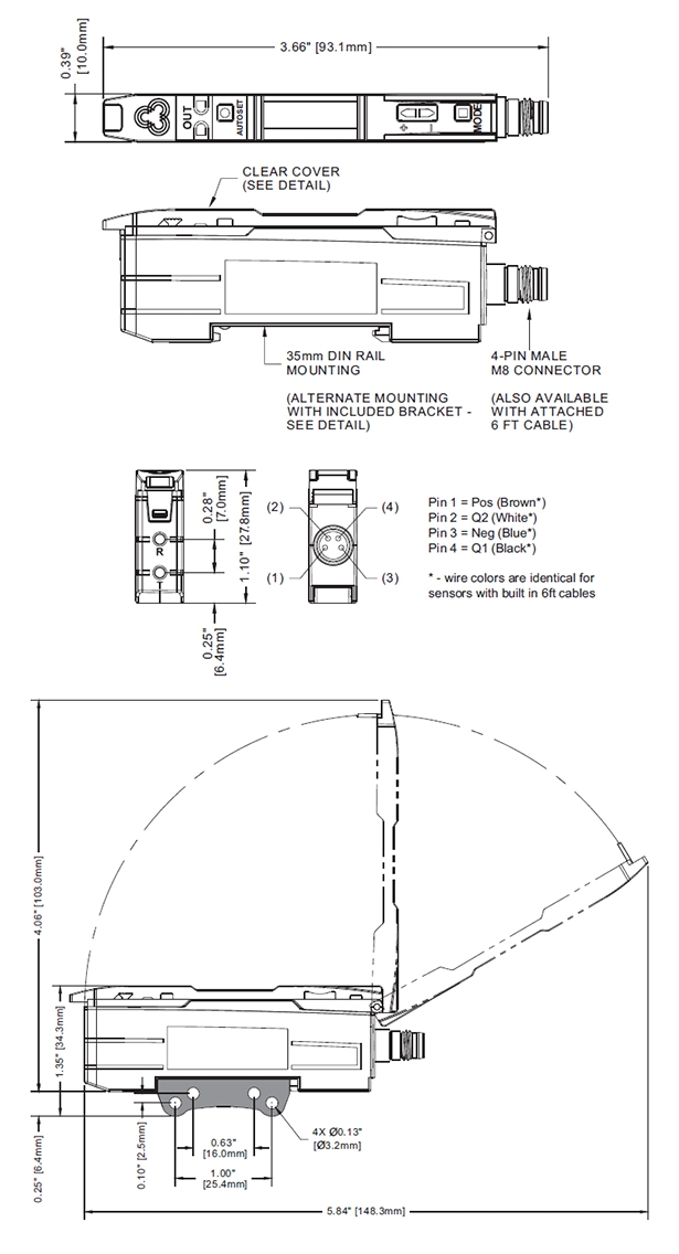
Dimensions

Showing 1–12 of 21 results
-

DFS11IC
$128.70 Add to cart -

DFS11R
$128.70 Add to cart -

DFS11RC
$128.70 Add to cart -

DFS12NI
$118.32 Add to cart -

DFS12NIC
$118.32 Add to cart -

DFS12NR
$118.32 Add to cart -

DFS12NRC
$118.32 Add to cart -

DFS12PI
$118.32 Add to cart -

DFS12PIC
$118.32 Add to cart -

DFS12PR
$118.32 Add to cart -

DFS12PRC
$118.32 Add to cart -

DFS21I
$132.31 Add to cart
