Fundamentals of Photoelectric Sensing

Today’s photoelectric sensor is one of the most versatile non-contact sensing devices known to man. The reliability of photoelectric “eyes” or “sensors” took a giant leap forward in the early 1970s when the light-emitting diode (LED) replaced the fragile incandescent light source.
This solid-state light source also enables the designer to eliminate most problems previously caused by ambient room light. Modern pulse-modulated photoelectric sensors respond only to the light emitted by their own light source.
This capability allows the sensor to be very sensitive and responsive to small light changes that occur to the light beam path between the light source lens and the receiving lens.
For an object to be detected, it must affect the intensity of the light beam reaching the sensor’s light detector in one of two ways:
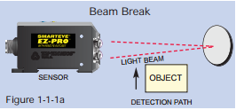 The object must break or diminish an existing light beam path between the light source lens and receiver lens — Beam Break mode (see Figure 1-1-1a).
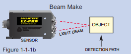 The object itself must diffuse or reflect the light beam to the receiving lens — Beam Make mode (see Figure 1- 1-1b).
One sure way to simplify the selection of a photoelectric sensor to fit your application is to remember that you only have two choices — Beam Make or Beam Break.
Contrasting Light Levels:
The sensing task of any digital switching photoelectric sensor is to respond to and resolve the difference between the contrasting light levels and switch its output accordingly.
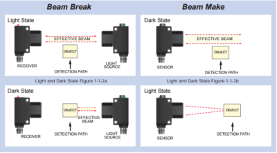
When operating in the Beam Break mode, the intensity of the light beam reaching the receiving lens is in its brightest or lightest state condition before an object is introduced into the light beam path. Introducing an object into the light beam path will block out, or diminish, the intensity of the received light beam, resulting in the darkest state condition (see Figure 1-1-2a).
In the Beam Make mode, the darkest state condition is before an object is placed in the light beam path. The lightest state condition is when an object is introduced into the light beam path so as to bounce, or reflect, the light beam to the receiving lens (see Figure 1-1-2b).
The amount of difference or deviation of the intensity of the light beam in its lightest state condition vs. the intensity of the received light beam in the darkest state is called “contrast.”
These contrasting light levels define the degree of difficulty of the sensing task. In real estate, it is well known that the three most important considerations are location, location, and location. In photoelectric sensing, the three most important considerations are contrast, contrast, and contrast.
Beam Break Sensing:
Opposed Mode:
In the Opposed Mode of sensing, two separate devices utilizing either lensed or fiberoptic light guides are used to make or break a beam.
One unit is the light source. The other is the receiver.
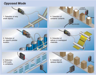
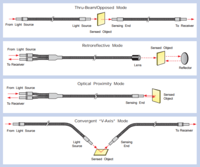
In this mode, the light source transmits a beam of light across the detection path to the receiver. Detection occurs when an object interrupts or sufficiently diminishes, the intensity of the received light beam (see Figure 1-2-1).
 Unfortunately, Beam Break sensing is often overlooked as a result of the initial cost of purchasing and installing two separate devices and the sometimes tedious task of alignment. However, the opposed mode of sensing has distinct advantages when detecting opaque products. lt provides the most reliable sensing method under very adverse conditions, such as dusty, dirty, and moisture-laden environments. Remember… when opaque, go Beam Break.
Retroreflective Mode:
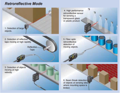
The Retroreflective sensor contains both the light source and receiving device in one housing. A unique dual-lens system or bifurcated fiber optic light guide establishes the transmitted light beam path and the returned light beam path on the same axis. When a retroreflective sensor or fiber is pointed or aimed at a reflector, the light beam is reflected back to the receiving lens or fiber (see Figure 1-3-1). Sensor alignment with a prismatic reflector can be skewed by 10 to 15 degrees and, still a strong light beam will return to the receiving lens on exactly the same axis as the original transmitted light beam.
 To detect the presence or absence of objects, the light beam path is directed across the detection path so that passing opaque objects interrupt the light beam. When the light beam is broken or when the intensity of the received light beam is reduced below a threshold level, the sensor responds by switching its output.
When sensing small parts, the recommended choice is opposed to mode sensing using fiberoptic light guides. The retroreflective sensor is generally low in cost and easy to install. However, care must be taken to ensure that shiny objects passing near the sensor do not reflect a light beam off the surface of the object strong enough to accidentally switch the sensor’s output. This undesirable characteristic of the retroreflective sensor is referred to as proxying. To prevent proxying, the sensor’s light beam can be aligned at an angle of incidence that reflects the light beam away from the receiving lens. Another way to reduce proxying is to polarize the light beam. Polarized light helps to ensure that only the light beam reflected off the prismatic reflector reaches the sensor’s receiver. While reducing the response to light reflected off the surface of the sensed object, polarizing reduces sensing range.
Transparent/Shiny Object Detection:
In the past, the retroreflective sensor has been the most effective choice when detecting opaque objects. However, recently things have changed. Thanks to advances in technology, the new RetroSmart™ retroreflective sensor can – absolutely, without fail, detect ANY transparent/translucent or shiny object. The RetroSmart™ sensor provides a single, non-chattering output for each transparent PET bottle or shiny metal can that passes through the sensor’s narrow, red light beam.
Gap Sensors:
Gap sensors are an excellent choice to sense a distinguishing change or object on a continuous web or roll of materials. By using opacity mode sensing techniques that utilize a light source capable of penetrating through the web of materials, gap sensors can register slight contrasting light level changes and produce an output signal for a specific machine operation.
A significant advantage of opacity mode sensing with TRI-TRONICS® gap sensors is that end-users do not need to be concerned with web flutter or ambient light, including strobe flashes. Depending on what you are trying to sense, opacity mode sensors can give you the desired output signal to perform machine functions. Typical applications include sensing labels on a roll, sensing registration marks on printed packaging material, and splice detection on continuous webs of material. Since opacity mode sensing distinguishes the light level change as light passes through a web of material, the web must be translucent or transparent. Most webs of packaging material such as film, metalized films, and paper do allow light to pass through. Opaque materials such as aluminum foil do not allow light to pass through and, therefore, cannot be used in opacity mode sensing.
MARK•EYE®
 The MARK•EYE® sensor is designed to see printed registration marks on most packaging materials on a continuous web. By detecting the contrasting light level difference between the background material and the registration mark on the web, the sensor’s output signals to perform a machine function.
LABEL•EYE®
The LABEL•EYE® sensor is designed specifically to sense a variety of adhesive labels on a continuous roll. It works by detecting the contrasting light level change that penetrates through the backing material of a web and a self adhesive label. The function of the LABEL•EYE® is to look through the backing paper to detect the “gap” between the labels and signal the labeling machine to stop the dispensing mechanism before the label is completely dislodged from the backing material. With the next “up” label protruding off the end of the peeler plate, it is now perfectly positioned to be applied to the next product as it passes by on a conveyor.
Optical Proximity Mode:
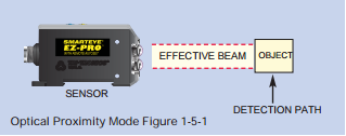 Optical Proximity sensors contain both the light source and the receiver in one common housing. The light source lens shapes the light beam into a diverging column of light that, with distance, increases in width and decreases in intensity. A wide-angle receiving lens is used to collect the reflected light beam off the surface of the object to be detected (see Figure 1-5-1).
A bifurcated fiber optic light guide can also be utilized as the light passes through the fiber optic light guide. The light is reflected off the object and passes back through the fiber to the sensor’s receiver.
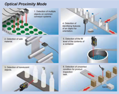
lt is often difficult, if not impossible, to access both sides of the detection path of objects moving past the sensing site. When this circumstance occurs, the Beam Make mode of sensing is the only choice. For example, when attempting to detect each item in a row of objects resting on a common conveyor belt, the proximity sensor is recommended. In this situation, the proximity sensor must resolve the difference between the contrasting light levels reflecting off the object vs. light reflecting off the conveyor belt.
The suppression of light reflecting off shiny objects in the background can be enhanced by the proper positioning of the sensor. If the angle of incidence to the reflected light beam is adjusted so that the light beam path does not return to the receiving lens, the proximity sensor will only respond to the light-diffusing or reflecting off the object itself.
Unfortunately, there are many situations when the intensity of the light reflected off the object is not much different than the intensity of light reflected off background objects. In applications when the differential between these contrasting light levels is minimal, a high-performance sensor equipped with high gain amplifiers and the contrast indicator is recommended. As a result of the diverging light beam, it is sometimes necessary for small objects to be as near as 1/8 inch to the receiving lens or fiber tip to be detected. Larger objects can be detected at a distance of up to 6 feet or more in this mode.
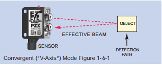
Convergent (“V-Axis”) Mode:
The convergent mode of Beam makes sense and is very similar to the proximity mode. The convergent beam sensor, like the proximity sensor, responds to a light beam path that reflects off the surface of the object. However, the lensing system of a convergent (also referred to as “V-Axis”) sensor converges the light beam into a small spot of light at a distance of a few inches, precisely at the receiving lens focal point. Using this technique provides an effective method of enhancing background suppression, while directing, by reflection, a very strong light beam on a direct path to the receiving lens. In addition to improving background suppression, convergent sensing is very useful for small parts detection and for the detection of printed identification data.

 Fiberoptic light guides can also be used in a convergent mode for “V-Axis” sensing. Simply direct two fibers at the target in a “V” configuration and small parts or the contrasts of an object can be detected.
Color Perception for Detecting Registration Marks:
Registration Mark Sensing:
 The White LED Light Source in our sensors is the best choice for detecting the widest variety of colored registration marks on today’s packing material. White Light enhances performance when detecting dark-colored registration marks on dark-colored webs of materials. In addition, the SMARTEYE® COLORMARK II sensor is equipped with Red, Blue, White and Green LED light sources. These colors are useful in applications when the preferred White Light Source does not optimally perform; i.e., a White or Blue LED light source is recommended to detect pale yellow marks on a white background.
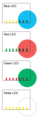
Imagine yourself viewing a printed red mark on white paper stock. The red mark looks dark in contrast to the white paper. Now, imagine placing a red transparent filter in front of your eye while trying to view that same red mark. The red mark now becomes difficult, if not impossible, to see. lf the sensor is equipped with a red LED, the sensor would have the same problem. Now, imagine yourself viewing that same red mark through a green filter. The white background now appears bright green, but the red mark appears black or very dark. That’s the contrast we are looking for! Equipping the sensor with a green LED provides the sensor with the same advantage as the green filter did for your eye. Now, the red mark provides more than adequate response to the contrasting light reflecting off the white background.
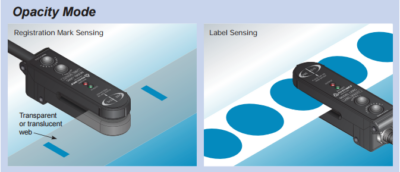
Opacity Mode Sensing:
The MARK•EYE® offers an excellent solution for opacity mode sensing. It is a slot sensor optimized to see printed registration marks on transparent, translucent, and metalized film on a continuous web of materials. Since the MARK•EYE® operates in the opacity sensing mode, the color of the registration mark simply doesn’t matter.
Optical Proximity Mode:
The MARK•EYE® PRO has been designed to detect the widest variety of color marks on the widest variety of web colors. It is optimized for high-speed detection of registration marks on opaque materials.
When another color of LED is desired, the COLORMARK II is an excellent choice. With the Red, Blue, Green, and White LEDs, seeing the registration mark has never been easier.
Other Color Perception Tasks:
The SMARTEYE® COLORWISE™ sensor is extremely useful in object sensing tasks when a difference in color is the only distinguishable feature. An example of an application where color perception is extremely useful in object sensing is identifying the contents of a container by the mere color of its cap. Please note that not all similar shades of the same color can be resolved; however, many can.
The SMARTEYE® COLORWISE™ is designed for color perception and recognition. All models are equipped with high gain amplifiers that provide excellent resolution in applications that require color-to-color, or shade-to-shade capability. Individual Channel Monitors (X4) provide visual feedback for color matching, and signal strength, increasing user confidence in application solution success.
Luminescence Sensing:
Luminescence Sensor:
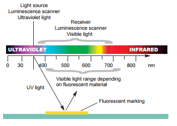 The SMARTEYE® STEALTH-UV sensor is a special purpose sensor designed to detect the presence of invisible fluorescent materials contained in special chalks, inks, paint, greases, glue, and optical brighteners found in labels, paper, tape, string, etc. The sensor contains an ultraviolet (UV) solid-state light source that is used to excite the luminescent materials to fluoresce in the visible range. The sensor’s detector then responds to the visible fluorescing light. When the received fluorescing light level, as displayed on the Contrast Indicator, reaches a level of “4” or above, the NPN and PNP output transistors will switch to the opposite state.
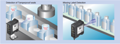
Typical Luminescence Sensor Applications:
- Detection of tamperproof seals
- Clear label detection
- Detection of invisible registration marks
- Product orientation
- Verification of the presence of adhesives
- Verification of pull tabs on packages
- Tape or splice detection of web
- Verification of glue on paper, plastic, or transparent materials
- Thread break detection
- Flaw detection using chalk or invisible marks on lumber/wood products
- Detection of the presence of a critical component in a complex assembly
Range:
The sensing range specification provided by sensor manufacturers is typically the maximum absolute sensing range under ideal circumstances.
In the opposed mode of sensing, maximum range is defined as the absolute maximum distance allowable between the light source and the receiver.
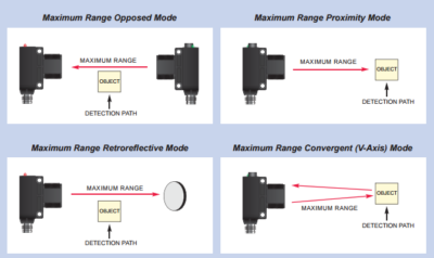
In the retroreflective mode of sensing, it is the absolute maximum distance between the sensor and the prismatic reflector.
In the proximity mode of sensing, the maximum range is the absolute maximum distance between the sensor and the sensed object.
However, these maximum sensing range specifications are for reference only. That is because these range specifications are taken under ideal conditions, with clear lenses, and in very clean environments. These conditions are not found in the vast majority of industrial applications.
Many manufacturers supply “excess gain” charts that plot range vs. signal strength obtained above the necessary level to trip the output of the sensor. These charts are plotted with the gain adjustments at maximum. In the Beam Break mode, the target/object is larger than the effective light beam and is always opaque.
When operating in the retroreflective mode, there is no way to obtain the effect of light reflecting off the sensed object.
 In the Beam Make mode, the object is larger than the effective light beam, is perfectly flat, and has a 90% reflective white surface. In addition, in the Beam Make mode, there is no way to obtain the effect of light reflecting off background objects from excess gain charts.
In summary, excess gain charts totally ignore signal strength generated by the Dark State condition.
TRI-TRONICS® unique Contrast Indicator provides actual signal strength indications that provide for perfect alignment by ascertaining actual response to the intensity of the received light. TRI-TRONICS® sensors equipped with Contrast Indicators provide an instantaneous real-time indication of the received light intensity at any range.
Contrast signal deviation charts are available on all sensors equipped with the Contrast Indicator. These charts are extremely helpful in determining if the sensor you have selected will adequately perform your particular sensing task at the desired range. Simply reference the amount of contrast deviation required to perform the sensing task in your environment, and compare it to the performance chart of the sensor you have selected to determine if the sensing range is adequate.
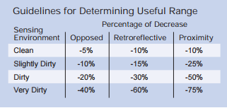
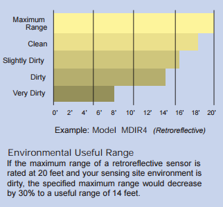
For TRI-TRONICS® sensors not equipped with Contrast Indicators, range guidelines charts are available that indicate recommended maximum sensing ranges. To estimate a useful range in your environment, simply decrease the specified maximum range by the percentage indicated in the following table.
Environmental Considerations:
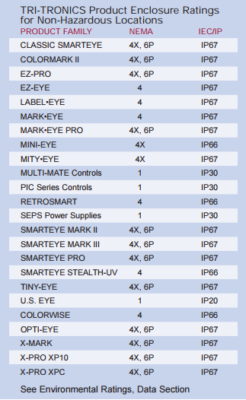
When selecting the appropriate TRI-TRONICS® sensor to fit your application, sensing site environmental conditions should always be considered. All TRI-TRONICS® products are designed with enclosures or housings that provide varying degrees of protection against special environmental conditions. The accompanying table lists the NEMA and IEC/IP Standards that apply to individual TRI-TRONICS® sensors and control enclosures.
Consult factory for RoHS compliance
Contrast Indicator Guaranteed Performance:
Contrast Indicator Guarantees Performance:
By viewing the Contrast Indicator readings during installation, the position that generates the largest amount of contrast deviation can be determined. Maximizing contrast deviation in any sensing application results in the guarantee of maximum performance and reliability.
Contrast Indicator Verifies Performance:
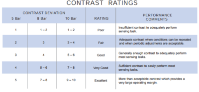
Performance of any SMARTEYE® can be diagnosed at the sensing site by observing contrast deviation as displayed on the Contrast Indicator. To ascertain deviation, simply subtract the lowest (Dark State) reading from the highest (Light State) reading and compare the resulting number to the contrast rating system below.
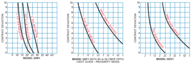
Contrast Performance Charts Verify Sensing Range:
These charts are extremely helpful in determining if the SMARTEYE® you selected will adequately perform the sensing task at the desired range. Simply reference the amount of contrast deviation required to perform the sensing task in your environment and compare it to the performance chart of the SMARTEYE® you have selected to determine if the sensing range is adequate. Shown below are typical performance charts on (3) Model SD SMARTEYE® Sensors.
Light Source Guidelines:
INVISIBLE INFRARED LIGHT SOURCE (880nm)
- Best choice in most opaque object sensing tasks
- Provides the longest possible sensing range in either Beam Make or Beam Break sensing modes
- Best choice in hostile environments; useful in penetrating lens contamination
- Preferred for use with small glass fiberoptic light guides Note: Do not use IR light with plastic fiberoptic light guides
- Preferred when sensing dark-colored objects in the proximity (Beam Make) mode, i.e., black, blue, green, etc.
- Useful in penetrating containers for verification of contents; also useful in detecting overlapped splices in dense materials
- Color perception; tends to favor blue colored objects
BLUE LIGHT SOURCE (480nm)
- Useful for detecting translucent, transparent, plastic, or glass objects in the retroreflective mode when using the R4 optical block
- Used as a blue filter for color perception advantages, i.e. resolving yellow vs. white colored objects or printed registration marks
RED LIGHT SOURCE (660nm)
- Best choice for use with plastic fiberoptic light guides
- Useful when sensing translucent objects in proximity (Beam Make) mode
- Useful when sensing transparent objects in fiberoptic retroreflective (Beam Break) mode
- Can be polarized for retroreflective (Beam Break) sensing to reduce proxying on shiny objects
- Opposed fiberoptic light guides can be polarized for sensing some translucent plastic containers; consult the factory for details
- Used as a red filter for color perception advantages
WHITE LIGHT SOURCE
(Broadband Color Spectrum)
- Best choice for detecting all printed registration marks on packaging material
- Recommended for detecting dark-colored objects in the proximity (Beam Make) mode
- Best choice for sorting colored objects
Optical Block Selection:
Interchangeable optical blocks provide a universal application to sensors in any sensing application. Select the sensor first, then choose the optical block that matches the spot size and target.
| Classic Series | Pro & Miniature Series | |
| Proximity Mode Sensing | ||
| Wide beam optics are useful for short-range sensing of transparent, translucent, or irregular-shaped shiny objects. | O2 | O4 |
| Narrow beam optics are useful in long-range sensing of medium to large size objects. | O1, O1G | O5 |
| Adapts sensors to glass fiberoptic light guides. | F1 | F4 |
| Adapts sensors to plastic fiberoptic light guides. | – | F5 |
| Retroreflective Mode Sensing | ||
| Very narrow beam optics are designed to sense reflectors or reflective materials at a long-range. Designed for Beam Break sensing | R1 | R4 |
| Polarized to reduce response to “hot spot” glare from the shiny surface of the detected object. Use with a red or blue light source. | – | R5 |
| Adapts sensors to glass fiberoptic light guides. | F1 | F4 |
| Adapts sensors to plastic fiberoptic light guides. | – | F5 |
| Convergent Mode Sensing | ||
| Narrow beam optics that focus at a sensing range of 1″. Useful for sensing small parts or registration marks, and Also useful for proximity sensing (range of 1″ to 5″) to minimize response to reflected light from background objects. | V1, V1G | V4, V4A |
| Narrow beam optics that focus at a sensing range of 1.5″. Useful for sensing small parts, and Also useful for proximity sensing (range of 1.5″ to 8″) to minimize response to reflected light from background objects. | – | V6 |
| Narrow beam optics that focus at a sensing range of .5″. Useful for sensing small parts or registration marks. Also useful for proximity sensing (range of .25″ to 5″) to minimize response to reflected light from background objects. | – | V8 |
Fiberoptic Light Guides:
When you shine a flashlight into one end of either flexible plastic or glass fiberoptic light guide, you will see light shining out the other end. The ability to guide light from the sensor to the target provides many advantages in photoelectric sensing.
Fiberoptic Light Guides are flexible and small enough to fit into difficult sensing areas. This allows the sensor to be located in a more convenient location— out of harm’s way. Fibers are resistant to high temperatures, vibration, condensation, and corrosion.
One of the main advantages of glass fiberoptic light guides is that they can be sized and shaped to provide an optical advantage. When fiberoptic light guides are utilized, they become the optics of the sensing system.
At the sensing site, the size and shape of the fiber optic bundle carrying the light control the size and shape of the transmitted light beam. The size and shape of the fiberoptic tip control the effective viewing area of the sensing system. Lenses are available to gain an optical advantage to the sensing tasks.
Our Miniature Glass Fiber Optic Light Guides combine the superior high-color resolution of glass fibers with the size and flexibility of plastic fibers. The tighter bend radius allows you to reach more areas with ease.
Response Time/Operating Speed:
Another very important factor in the selection of a photoelectric sensor is the sensor’s ability to resolve input events occurring at rapid rates. Unfortunately, response time specifications provided by some photoelectric sensor manufacturers are sometimes vague or, at best, difficult to interpret. It should be noted that there is a difference between response time and operating speed.
Response Time is the length of time it takes for the output of the sensor to switch when a change from the lightest state to the darkest state (or vice versa) occurs. This can be important when attempting to locate the exact position of an object moving at a high velocity. Operating Speed is the maximum output switching rate the sensor can achieve. This rating is usually expressed by the maximum rate of input events that can be resolved under set conditions.
These conditions generally involve input events that are equally spaced apart, i.e., the length of time the sensor will be in the Dark State condition is equal to the length of time in the Light State condition. This is referred to as a 50-50 duty cycle. If the duty cycle of the input event is other than 50-50, attention should focus on the minimum duration of time the input event will spend in either the Light State or the Dark State condition.
The shortest duration of time spent in either state should then be compared with the minimum Light State/Dark State response times as stipulated in the sensor’s specifications.
A word to the wise: Beware, you cannot expect the sensor to achieve the specified minimum response time or maximum operating speeds under all sensing conditions without making some adjustments to either the gain or offset settings.